Terminology and units
A basic guide to electricity, EMFs and the terminology used on this site.
Throughout this site, "EMFs" is used to stand for "electric and magnetic fields". For the power frequency fields that are considered on this website, the electric field and the magnetic field occur separately. By referring to EMFs we are considering both.
"EMFs" can also stand for "electromagnetic fields". Some people use this to mean specifically the situation at higher frequencies where the electric and magnetic fields are coupled together and have a fixed relationship to each other.
Electric and magnetic fields are measured in units, and each has a different one associated with it. These come in different sizes and some countries use different units to those used in the UK. Below we detail what the UK units are and how to convert between each type of unit.
Electric Fields
Electric fields are usually measured in volts per metre (V/m)
Multiple is used for large fields: 1 kilovolt per metre (kV/m) = 1000 V/m
Magnetic Fields
Magnetic fields are usually measured in microteslas (µT)
Multiple used for large fields: 1 millitesla (mT) = 1000 µT
or small fields: 1 nanotesla (nT) = 0.001 µT
Other units are sometimes used:
1 milligauss (mG) = 0.1 µT (milligauss is common in the USA)
1 ampere per metre (A/m) = 1.25 µT
(this conversion for amperes per metre is only true for air and other non-magnetic materials. It changes in the pressure of magnetic materials such as iron.)
Voltages and currents can be pictured as electrical pressure. The analogy is often used with water in a pipe; voltage is analogous to the pressure of the water.
Voltage is measured between two objects and is the potential difference between the two points. However, it is conventional to define the Earth as being at zero volts. Then we can talk about the voltage of a single point or conductor as compared with Earth.
Current is the flow of electricity. A voltage will always try to drive a current. The size of the current that is driven depends on the resistance of the circuit. If the voltage occurs across an air gap, for instance, a negligible amount of current will flow. If the voltage occurs across a conductor, a current will flow.
Power is the product of voltage and current. In the electricity industry the voltage is kept constant and the current is changed to vary the power transferred.
The relationship “power = voltage times current” applies no matter what units you use for measuring the various quantities, provided the units are consistent with each other. The simplest units to use are volts, amps and watts:
• watts (W) = volts (V) x amps (A)
• kilowatts (kW) = kilovolts (kV) x amps (A) = volts (V) x kiloamps (kA)
• megawatts (MW) = kilovolts (kV) x kiloamps (kA) etc
The power is transmitted through the transmission and distribution networks to the end consumer. To transmit a given power, you can have a high voltage and a low current or a low voltage and high current.
However, current causes heating. This can be thought of as the electrons that are carrying the current bumping into the atoms of the wires, with these collisions producing heat. The heating increases more at higher currents.
The relationship between voltage, current and power means that using low voltage and high current will waste more energy by heating the wires. That is why for large transfer of power, high voltage is used to reduce the losses due to heating.
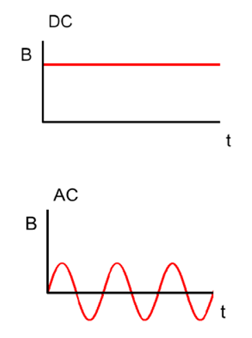
In a direct current (DC) circuit, the voltage and the current continue in the same direction all the time. Battery-operated electronics and car electrics are examples of DC circuits.
Most power transmission uses alternating currents (AC). DC may also be used in power systems where it is necessary to transmit power over very long distances or where you want to connect two different AC systems, but you don’t want to have to keep them synchronised (e.g. Britain and France).
The current within DC cables remains constant, however current in AC cables will periodically reverse direction (+ to -) based on its frequency, and in the case of 50 Hz (which is the frequency used in the UK), that's 50 times a second.
DC fields have different exposure guidelines to AC fields, so it is important to know what frequency equipment is operating at.
When you look at a typical overhead line it usually has three sets of wires on one side, three on the other, and one at the top, but why?
Each side of the overhead line is a circuit, and each circuit has three ‘phases’. Electricity is transmitted using three phases because it is more efficient at transferring power, needing less wires (or conductors) than if two or four phases were used. The wire at the top is an earthwire to protect the overhead line from lightning strikes.
The three phases carry voltages and currents which are nominally 120 degrees out of phase with each other. They are often named after colours as convenient labels; usually red, yellow and blue.
The three phases are on each side of a pylon, each produce magnetic fields which interact with one another. This can affect the magnetic field an overhead line produces, to find out more read the ‘Phasing, transposed phasing, untransposed phasing, and optimum phasing’ tab below.
Three-phase electricity leads to another subtlety in voltages. The voltage between any two of the three phases is 1.73 (the square root of three) times larger than the voltage between any one phase and earth. You therefore have to decide whether to give voltages between phases or phase-to-earth. The electricity industry almost always gives phase-to-phase voltages. Thus 400 kV is 400 kV phase-to-phase and only 230 kV phase-to-earth. The exception is the final distribution voltage, which can be given either way. 230 V is phase-to-earth and 400 V is phase-to-phase.
Phasing refers to the way the phases on each side of a pylon are arranged relative to each other. From the above section on phases remember that phases are given labels of red, yellow and blue. Phasing is one of the factors that affects the overall electric and magnetic fields produced by an overhead line.
Transposed and untransposed phasing are two ways that these phases can be arranged.
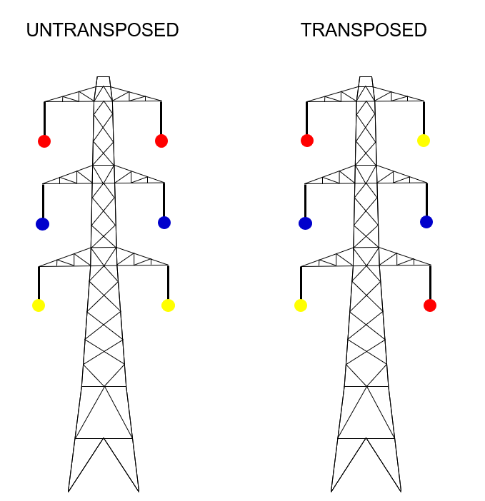
Untransposed phasing has the phases in the same order on either side of the pylon. Because the order of the phases is the same, the magnetic fields are in the same direction, and they add together. This produces a combined field that is larger to the side of the line compared with transposed phasing.
In transposed phasing the phases are in the opposite order on each side of the pylon, so the magnetic fields are going in opposite directions resulting in more cancellation. The cancellation is not perfect because you are closer to one circuit or the other, but it does reduce the fields to the side of the overhead line.
In general, the magnetic fields from transposed lines reduces more quickly than for untransposed lines, as shown in the simple example in the graph to the right. In reality, overhead lines are more complex so the effect may not be as large as in this example.
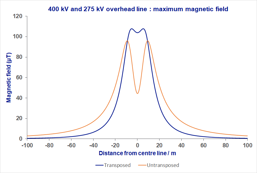
Most transmission voltage overhead lines in the UK have transposed phasing but this is not always possible for every overhead line.
Optimum and non-optimum phasing
In the discussion and example above the currents are assumed to be moving in the same direction on either side of the pylon. If they are moving in opposite directions, the situation that produces lower fields to the side of the overhead line is reversed and therefore untransposed phasing would produce the lower fields to the side of the line. The term 'optimum phasing' is used to describe circuits that have been arranged to produce the lowest fields to the sides of the line.
Voltages are changed by a transformer. Transformers are very efficient and absorb very little power. A substation is simply one or more transformers plus their associated equipment like switchgear and protection systems.
With AC, the only way of storing large amounts of energy over significant periods of time is to convert the electrical energy into some other form of energy that can be stored, for example gravitational potential energy in a pumped storage system.
A field is a general concept in physics for a region of space where a quantity exists at each point in the region and can exert an influence over objects in that region. You can have a field of different types depending on the property that varies over space, for example temperature, gravity, or electric and magnetic fields.
For overhead lines it is more helpful to think of both electric and magnetic fields as the regions around electrical conductors in which the effect of the field can be measured.
Electric and magnetic fields are produced independently of each other, with the electric field produced by the voltage, and the magnetic field by the current.
The field at any point is produced by all the sources around it. If one single source is dominant, the field will have a simple shape. If there are several significant sources, the field can be quite complicated.
Radiation is a transfer of energy that moves from one place to another. This can take the form of either particles or waves.
Although electric and magnetic fields are produced separately, with electric fields produced by voltage and magnetic fields by current, once they have been produced, they can interact with each other and couple together as radiation. This effect is stronger for higher frequencies and weaker at lower frequencies and depends on the distance from the source of the fields. For 50 Hz fields (the frequency of the UK electricity system) this effect is extremely small and these fields would not commonly be referred to as radiation.
Another more common use of the term ‘radiation’ is to refer to ‘ionising radiation’, which can also be due to either particles or electromagnetic waves, for example x-rays, gamma rays, and alpha and beta particles. They are called ‘ionising’ because they have enough energy to break chemical bonds, which is how they cause damage to the body. EMFs do not have enough energy to break chemical bonds and are not ionising radiation.
Exposure to external electric and magnetic fields can cause induced currents to flow within the body, which if high enough can cause acute biological effects. The most sensitive response is ‘magnetophosphene’ occurrence which is a flickering sensation around the periphery of vision produced by induced currents in the retina at high magnetic fields. The exposure guidelines in the UK are based on limiting these induced currents. The International Commission on Non-Ionizing Radiation Protection (ICNIRP), who formulate the guidelines which have been adopted by UK Government, recognise that effects on the retina, specifically magnetophosphenes, are the best indicator of a biological response threshold given current knowledge.
Dosimetry is the assessment of the size and distribution of induced fields and currents within a human that is exposed to EMFs. The most accurate way to determine how much current is induced is to perform a numerical calculation. The body is split into millions of small elements called “voxels”. Each voxel is assigned a conductivity appropriate to the tissue type it forms part of. Then computers are used to calculate the current induced in each voxel.
This is the method used to calculate EMF limits in the UK.